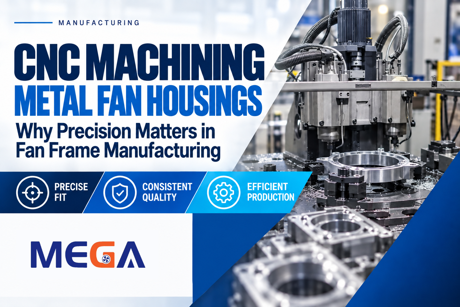
We recently filmed a run on one of our CNC setups: a rotary fixture plate holding several metal fan housing components at once, a multi-head machining station working across them, and the usual scatter of metal chips that comes with cutting aluminum or steel. It’s not a dramatic clip. But it’s a useful one for explaining a point that doesn’t come up often enough when people talk about cooling fans: the housing is doing more work than it looks like.
Table of Contents
ToggleThe Housing Is Not Just an Outer Shell
It’s easy to think of a fan housing as the part that keeps fingers away from the blades and gives the product something to mount to. Structurally, that’s true. But the housing is also the part that sets where everything else sits. The bearing bore has to land in the right place relative to the impeller. The mounting holes have to line up with whatever the fan is being bolted to, whether that’s a heatsink, an equipment panel, or another housing half. The motor has to seat squarely enough that the shaft doesn’t run off-center once the fan spins up.
None of that is negotiable after the fact. If the housing’s geometry is off, the rest of the fan is being assembled around a mistake, and the symptoms usually show up later as vibration, uneven wear, or a shortened bearing life, not as an obvious defect at the point of assembly.
What the Video Actually Shows
The clip shows several metal fan housing or frame components secured in fixtures on a rotary table, with multiple machining heads working on them in the same setup. That arrangement exists for a specific reason: fixturing several parts at once and machining them in the same pass is how a shop keeps the same features landing in the same place, part after part, rather than depending on an operator resetting a single part by hand each time.
We’re not going to attach a specific alloy, tolerance figure, or machine spec to this clip that we can’t stand behind in writing. What’s worth saying plainly is what the setup is doing: cutting mounting features, bores, or other machined details into metal fan components in a repeatable, fixtured process, rather than a one-off manual operation.
Why Repeatability Is the Actual Point
A single well-machined housing isn’t hard to produce. The harder problem, and the one CNC machining is actually solving, is making the hundredth one match the first one just as closely. For a metal fan housing going into a production run of hundreds or thousands of units, a few tenths of a millimeter of drift in a mounting hole or bearing bore, repeated across a batch, turns into an assembly line problem: fans that don’t seat the same way twice, extra fitting time, or units that pass inspection individually but behave inconsistently once installed.
Fixtured, multi-station machining is built around minimizing that drift. Holding several components in place at once and running them through the same machining heads means the geometry that mattered on part one is the geometry you’re still getting on part five hundred.
A General Path From Raw Metal to Finished Fan
Most metal fan housings and frames move through some version of the same broad sequence, though the specific steps and their order vary by part and by shop:
A raw or preformed metal component starts the process, whether that’s a casting, a stamped blank, or bar stock. CNC machining then cuts the features that have to be precise: bores, mounting holes, flat mating surfaces, and any structural cutouts. From there, the part typically goes through dimensional or feature inspection to confirm it actually matches the design before it moves on. Depending on the part, additional finishing steps may follow. Only after all of that does the housing become part of a finished fan assembly, brought together with the motor, bearing, and impeller.
We’re describing that as a general manufacturing progression common to metal fan components, not as a claim about the exact sequence, station count, or inspection method used for the specific parts in this video.
Where This Matters Most in Practice
Precision at the housing level tends to matter most where the fan itself is under more mechanical or thermal load: larger centrifugal fans and blowers, metal-framed units built for industrial or continuous-duty environments, and fans destined for equipment where a housing that doesn’t seat correctly means a bearing that wears out early rather than just a rattle. That’s a different set of stakes than a small plastic-framed fan cooling a low-duty consumer device, which is part of why our own product range spans both, from compact centrifugal blowers like the 100 x 100 x 25mm DC centrifugal fan up to larger 120 x 120 x 32mm blowers built for higher-demand equipment.
For OEM buyers, this is really a sourcing question as much as an engineering one: a supplier that can hold housing geometry consistent across a production run is a supplier whose fans will fit the same way on unit one thousand as they did on unit one. That consistency is also what makes custom cooling fan work possible in the first place, since a one-off design only pays off if it can actually be reproduced at volume without drifting off spec.
If you’re weighing fan construction alongside other selection factors, our earlier posts on bearing type, static pressure versus airflow, and choosing between axial fans, blowers, and centrifugal fans cover the other side of the decision: what the fan needs to do, once the housing it’s built on is dimensionally sound.
Talk to Us About Your Fan Housing Requirements
Whether you’re sourcing a standard blower, a centrifugal fan, or a fully custom cooling solution with a metal housing built to your specifications, our team can walk through what your application actually needs before quoting anything.