Function of 3 Pin Fan & 4 Pin Fan
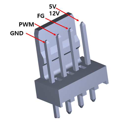
Most cooling fans will connect to a PC with a standard connector of some sort. Modern systems will typically use 3-pin or 4-pin dedicated fan headers, though standard MOLEX 4-pin peripheral connectors are also used. From left to right: A 3-pin connector, a 4-pin connector and a MOLEX connector.

3 Pin Fan
The 3 pin fan connector has three indicators (as per the number of wires): The first wire is for power (4 to 12 volts), 2nd is for ground and 3rd wire is for a tachnometric signal (speed sensor) this sensor monitors the fan speed and performance.
A tachnometric signal adjusts the level of power applied to the motor by transmitting the speed of rotation of the fan impeller at a nominal voltage between 5 to 12 volts. In this way, the fan speed is typically controlled by increasing or decreasing the voltage across the power cable.
Pinout
1 Ground
2 +5V ~12V
3 Tachometer
4 Pin Fan
4 pin fan headers are commonly found in modern motherboards. The 4 pin fan connector is slightly different from the 3 pin connector also works the same but the additional 4th wire is PWM (Pulse Width Modulation) used for controlling the power supply of the load and rotation speed of the fan impeller.
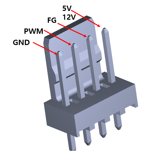
The duty cycle of the PWM signal controls the speed of the fan motor. The motor will be supplied with 12 V (for example )throughout, however, the duty cycle of the PWM signal decides how long the fan should be running or not. A duty cycle of 40% keeps the fan on for 40% of the total time period of the PWM signal, and the other 60% of the time it will remain off. The speed variation of cooling fans is within 30-100% of the rated speed, with the PWM technique and the minimum speed achieved by PWM fans being much lower than DC fans. The chassis and CPU temperature are the two factors that influence the speed of the cooling fans. The new technology advancements have brought firmware and software controlled PWM fans, where the speed is controlled according to the CPU or case temperature. The PWM fans are commonly seen as CPU coolers with higher power consumption.
PWM CONTROL SIGNAL
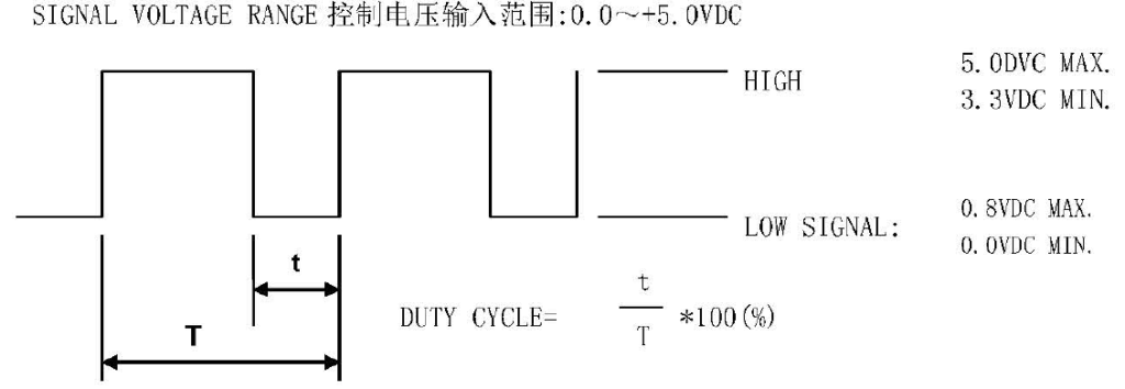
● THE PREFERRED OPERATING POINT FOR THE FAN IS 25K HZ
● AT 100 DUTY CYCLETHE ROTOR WILL SPIN AT MAXIMUM SPEED
● AT 0 DUTY CYCLETHE ROTOR WILL STOP
● WHEN CONTROL SIGNAL LEAD DISCINNECTEDTHE FAN WILL MAXIMUM SPEED
● AT 25K 3~5 DUTY CYCLETHE FAN WILL BE ABLE TO START FROM A DEAD STOP
● THE FAN SPEED CONTROL IS CLOSED LOOP
PWM CONTROL LEAD WIRE INPUT IMPEDANCE

2 ABSOLUTELY NO INTERNAL PULL UPNECTED
FG and RD Function Introduction
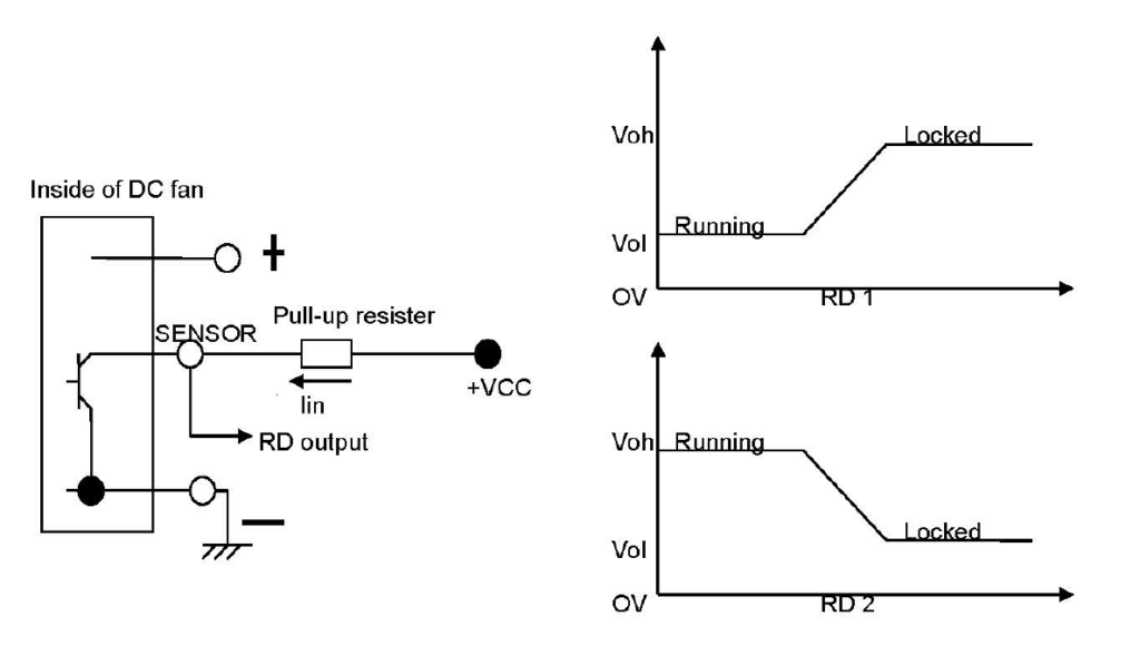
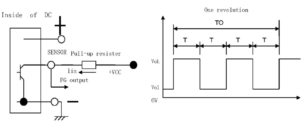
FG (Tach output type) Connection Diagram
Fan with FG function will creat a square wave output.You can know fan speed by sensing the output wave Frequency. Most dc fan have four pole.So when fan run for one round,there will be two high level pulse. About other Multipole brushless fan,high level pulse will be different.
But please notice if you want to sense it’s output wave,there is a external circuit. Please check the circuit Diagram below. There is no pull-up and VCC value limit.But please notice the Max Iin have to be small than 20mA.
Some fan have RD extra functionThere is a alarm signal output when fan stop workPlease notice there are Two kinds of signal output Different customer will need different alarm typePlease check the diagram belowRD alarm input voltage33V RD output current20MA
